Appearance
Sensoriamento
❤️ Pulso Amped Sensor
📚 Pulse Sensor Amped Getting Started Guide
Para melhor ligar ao corpo é necessário:
Velcro para prender o sensor no dedo conforme as imagens abaixo
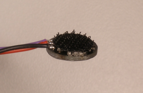
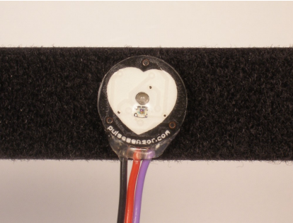
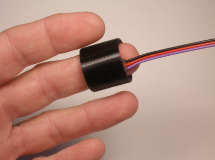
Adesivos transparentes para proteger o sensor da oleosidade dos dedos
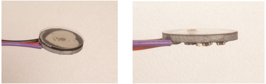
Conexão dos fios:
📷
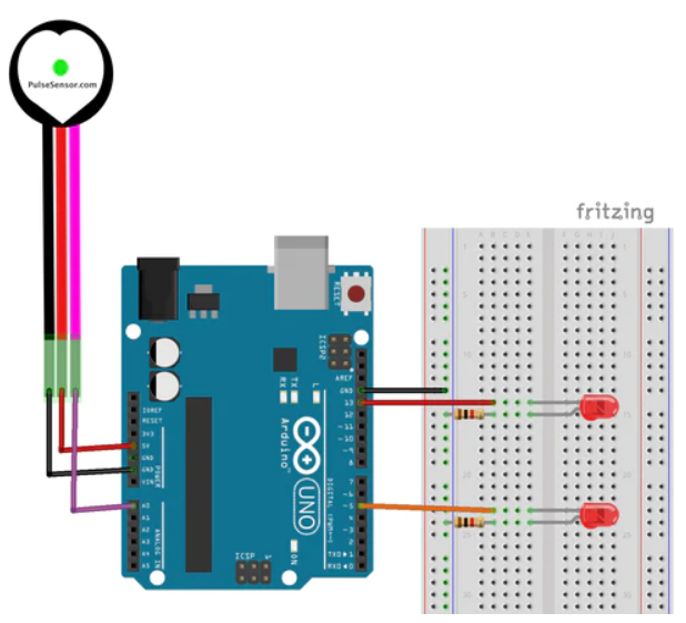
Fio amarelo/preto -> Analogico
Fio azul/vermelho -> GND
Fio verde/marrom -> 5V
Código
cpp
/******Necessário instalar biblioteca PulseSensor Playground******
   Code to detect pulses from the PulseSensor,
   using an interrupt service routine.

   Here is a link to the tutorial\
   https://pulsesensor.com/pages/getting-advanced

   Copyright World Famous Electronics LLC - see LICENSE
   Contributors:
     Joel Murphy, https://pulsesensor.com
     Yury Gitman, https://pulsesensor.com
     Bradford Needham, @bneedhamia, https://bluepapertech.com

   Licensed under the MIT License, a copy of which
   should have been included with this software.

   This software is not intended for medical use.
*/

/*
   Every Sketch that uses the PulseSensor Playground must
   define USE_ARDUINO_INTERRUPTS before including PulseSensorPlayground.h.
   Here, #define USE_ARDUINO_INTERRUPTS true tells the library to use
   interrupts to automatically read and process PulseSensor data.

   See ProcessEverySample.ino for an example of not using interrupts.
*/
#define USE_ARDUINO_INTERRUPTS true
#include <PulseSensorPlayground.h>

/*
   The format of our output.

   Set this to PROCESSING_VISUALIZER if you're going to run
    the Processing Visualizer Sketch.
    See https://github.com/WorldFamousElectronics/PulseSensor_Amped_Processing_Visualizer

   Set this to SERIAL_PLOTTER if you're going to run
    the Arduino IDE's Serial Plotter.
*/
const int OUTPUT_TYPE = SERIAL_PLOTTER;

/*
   Pinout:
     PULSE_INPUT = Analog Input. Connected to the pulse sensor
      purple (signal) wire.
     PULSE_BLINK = digital Output. Connected to an LED (and 220 ohm resistor)
      that will flash on each detected pulse.
     PULSE_FADE = digital Output. PWM pin onnected to an LED (and resistor)
      that will smoothly fade with each pulse.
      NOTE: PULSE_FADE must be a pin that supports PWM. Do not use
      pin 9 or 10, because those pins' PWM interferes with the sample timer.
*/
const int PULSE_INPUT = A0;
const int PULSE_BLINK = 13;    // Pin 13 is the on-board LED
const int PULSE_FADE = 5;
const int THRESHOLD = 550;   // Adjust this number to avoid noise when idle

/*
   All the PulseSensor Playground functions.
*/
PulseSensorPlayground pulseSensor;

void setup() {
  /*
     Use 115200 baud because that's what the Processing Sketch expects to read,
     and because that speed provides about 11 bytes per millisecond.

     If we used a slower baud rate, we'd likely write bytes faster than
     they can be transmitted, which would mess up the timing
     of readSensor() calls, which would make the pulse measurement
     not work properly.
  */
  Serial.begin(115200);

  // Configure the PulseSensor manager.

  pulseSensor.analogInput(PULSE_INPUT);
  pulseSensor.blinkOnPulse(PULSE_BLINK);
  pulseSensor.fadeOnPulse(PULSE_FADE);

  pulseSensor.setSerial(Serial);
  pulseSensor.setOutputType(OUTPUT_TYPE);
  pulseSensor.setThreshold(THRESHOLD);

  // Now that everything is ready, start reading the PulseSensor signal.
  if (!pulseSensor.begin()) {
    /*
       PulseSensor initialization failed,
       likely because our particular Arduino platform interrupts
       aren't supported yet.

       If your Sketch hangs here, try PulseSensor_BPM_Alternative.ino,
       which doesn't use interrupts.
    */
    for(;;) {
      // Flash the led to show things didn't work.
      digitalWrite(PULSE_BLINK, LOW);
      delay(50);
      digitalWrite(PULSE_BLINK, HIGH);
      delay(50);
    }
  }
}

void loop() {
  /*
     Wait a bit.
     We don't output every sample, because our baud rate
     won't support that much I/O.
  */
  delay(20);

  // write the latest sample to Serial.
 pulseSensor.outputSample();

  /*
     If a beat has happened since we last checked,
     write the per-beat information to Serial.
   */
  if (pulseSensor.sawStartOfBeat()) {
   pulseSensor.outputBeat();
  }
}
Output esperado:
BPM, Beat interval, Lastest Sample (Raw data)
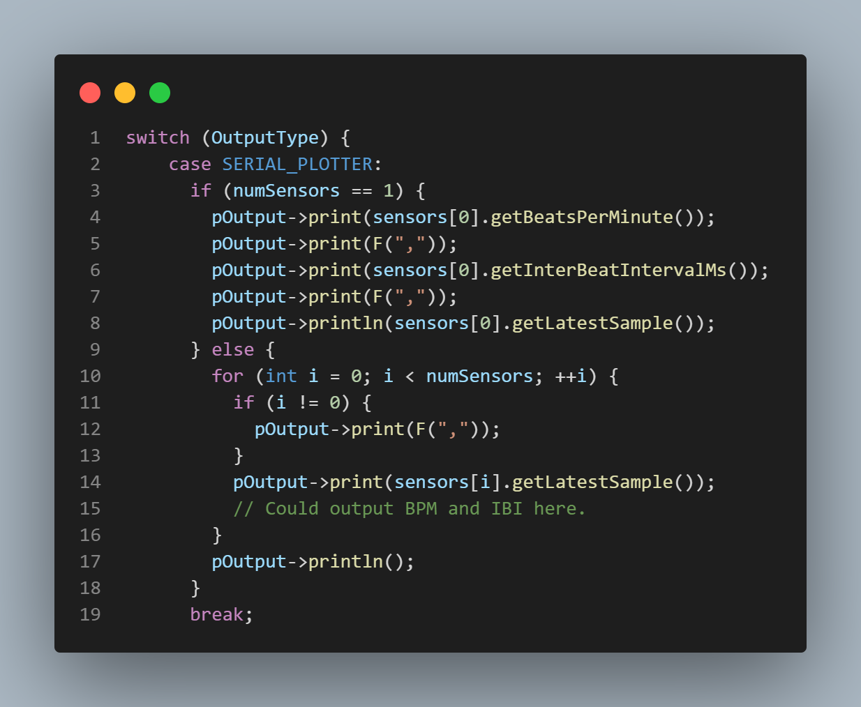
código para escrever na porta serial da pulseSensor library
💪🏼 EMG
📚 Myoware Muscle Sensor Interfacing with Arduino
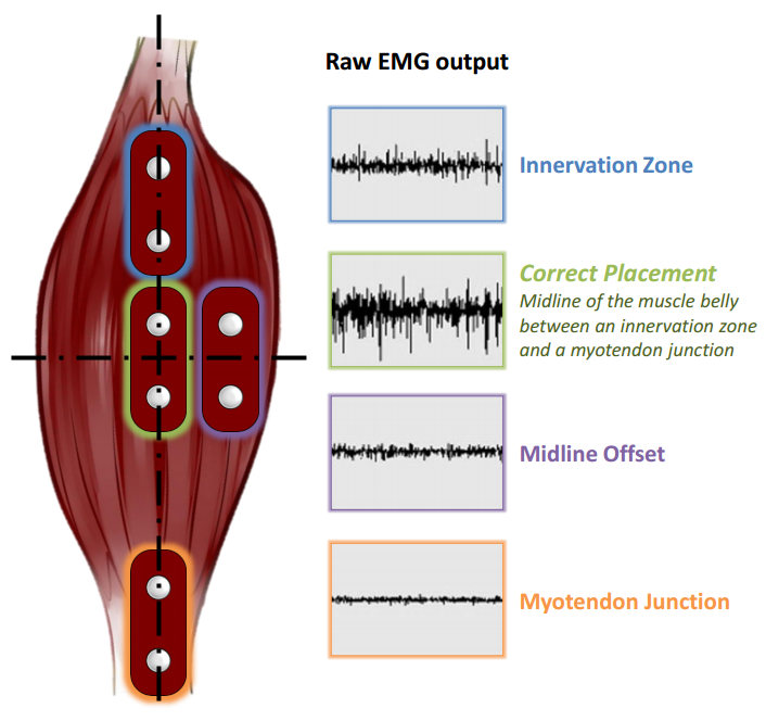
Para ligar o sensor ao corpo é necessário:
- Posicionar no musculo de forma que os sensores fiquem no meio do musculo que se deseja coletar a força realizada conforme demonstrado na figura 1.
- Posicionar o aterramento longe do musculo a ser analisado.
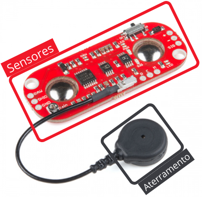
Conexão dos fios:
Fio azul Analogico
Fio verde GND
Fio vermelho 5V
Código:
cpp
const int analogInPin = A0;  // Analog input pin that the potentiometer is attached to
const int analogOutPin = 9; // Analog output pin that the LED is attached to

int sensorValue = 0;        // value read from the pot
int outputValue = 0;        // value output to the PWM (analog out)

void setup() {
  // initialize serial communications at 9600 bps:
  Serial.begin(9600);
}

void loop() {
	// read the analog in value:
	sensorValue = analogRead(analogInPin);
	// map it to the range of the analog out:
	outputValue = map(sensorValue, 0, 1023, 0, 255);
	// change the analog out value:
	analogWrite(analogOutPin, outputValue);

	// print the results to the Serial Monitor:
	Serial.print("sensor = ");
	Serial.print(sensorValue);
	Serial.print("\t output = ");
	Serial.println(outputValue);

	// wait 200 milliseconds before the next loop for the analog-to-digital
	// converter to settle after the last reading:
	delay(200);
}
// code from Arduino IDE: File > Examples > 03.Analogic > AnalogicInOutSerial
🧲 Sensor de Efeito Hall
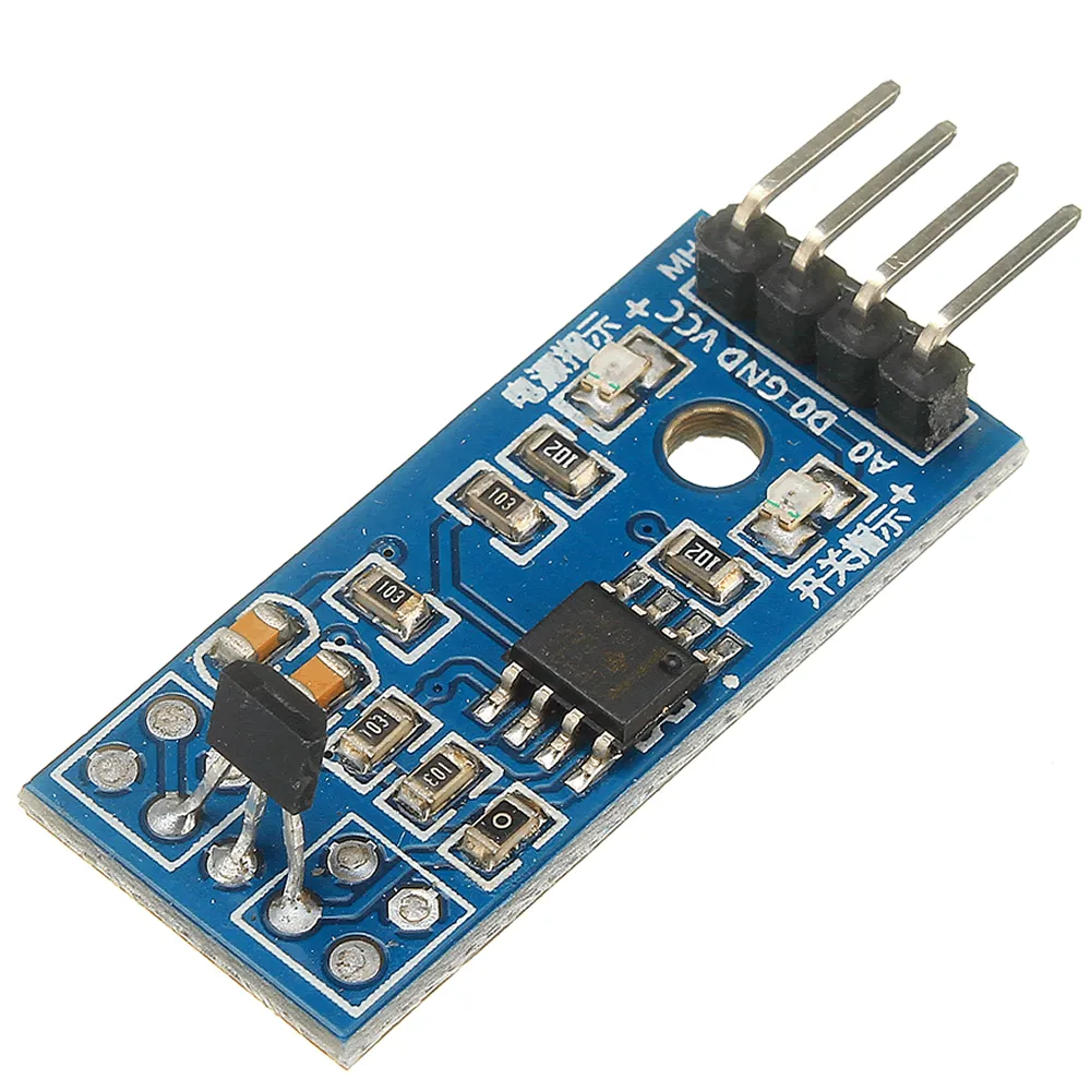 Figura 3 - Sensor de efeito Hall
 Conexão dos fios:
A0 - Analog pin
D0 - Digital pin
VCC - 5V pin
GND - Ground pin
Código:
cpp
int hall_din=10;
int hall_ain=A0;
int ad_value;
int i = 0;
int currentI = 0;

// for calculate the distance and velocity
#define PI 3.1415926535897932384626433832795
#define updateRate 1000 // time between each amount of time that we capture the magnet presence in milliseconds (just values multiple of 10)
#define radius 0.37 // m
float distance = 2*PI*radius;; // m
float lstTime; // last time that the sensor notice the magnet
float interval; // interval between the first and the last time that the magnet passed by the sensor in milliseconds
float velS = 0; // m/s
float vel = 0; //km/h
int RPXS = 0; // rotation per x seconds

void setup()
{
  pinMode(hall_din,INPUT_PULLUP);
  pinMode(hall_ain,INPUT);
  pinChangeSetup();
  Serial.begin(9600);
  Serial.println(distance);
  delay(2000);
}

void pinChangeSetup(){
  cli();
  PCICR = 1;
  PCMSK0 = 16;
  sei();
}

ISR(PCINT0_vect){
  cli();
  // debounce is necessary to not catch the magnet twice or more at the same read
  static unsigned long debounce = millis();
  if((millis() - debounce) > 300){
    debounce = millis();
    if(i == 1){
      lstTime = millis();
      currentI = i;
    }
    i++;
    // Serial.println(i);
  }
  sei();
}

void loop(){
  interval = millis() - lstTime;
  if(interval >= updateRate){
    lstTime = millis()
    RPXS = i - currentI;
    currentI = i;
    velS = (RPXS*distance/updateRate);
    velS = velS/(updateRate/1000);
    vel = velS*3600;
  }
  Serial.println(vel);
  delay(1000);
}
🕹️ Joystick
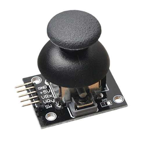 Figura 4 - módulo joystick KY-023
 Conexão do Joystick:
A1 - VRx
A0 - VRy
VCC - 5V pin
GND - Ground pin
none - SW
Código:
cpp
const int pinX = A0;
const int pinY = A1;

int valueX = 0;
int valueY = 0;
int outputValueX = 0;
int outputValueY = 0;

void setup() {
  Serial.begin(9600);
}

void loop() {
  // read the analog in value:
  valueX = analogRead(pinX);
  valueY = analogRead(pinY);
  // map it to the range of the analog out:
  outputValueX = map(valueX, 0, 1023, 0, 255);
  outputValueY = map(valueY, 0, 1023, 0, 255);

  // print the results to the Serial Monitor:
  Serial.print("X = ");
  Serial.print(outputValueX);
  Serial.print("\t Y = ");
  Serial.println(outputValueY);

  // wait 2 milliseconds before the next loop for the analog-to-digital
  // converter to settle after the last reading:
  delay(2);
}